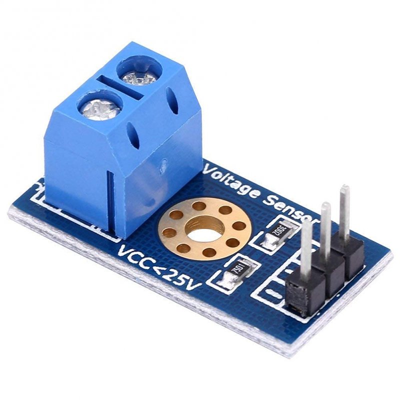
Description
The Arduino analog input is limited to a 5 VDC input. If you wish to measure higher voltages, you will need to resort to another means. One way is to use a voltage divider. It is fundamentally a 5:1 voltage divider using a 30K and a 7.5K Ohm resistor. Keep in mind, you are restricted to voltages that are less than 25 volts. More than that and you will exceed the voltage limit of your Arduino input.
SCHEMATIC OF VOLTAGE SENSOR
The Voltage Sensor is basically a Voltage Divider consisting of two resistors with resistances of 30KΩ and 7.5KΩ i.e. a 5 to 1 voltage divider. The following image shows the schematic of the Voltage Sensor Module with an input voltage limit of 25V.
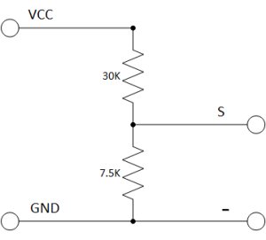
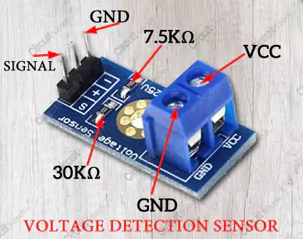
If you want to make your own voltage sensor that can measure voltages up to 25V like this Voltage Sensor Module, then you have to get a 30KΩ and a 7.5KΩ resistor.
اذا اردت صناعة سينسور شبيه بهذا لكن لقراءة قيم اكبر من 25 فولت فقط عليك اختيار قيم للمقاومات R1 و R2 بدل 7.5 و 30 كيلو اوم بحيث تعطي تحويل مناسب بين الـ 0 فولت والـ 5 فولت كي لا تنحرق الاردوينو
Example:
Find yourself a 9 volt battery(or any DC device with a voltage of 0-25v.) and connect it, your voltage sensor module and Arduino as shown below.
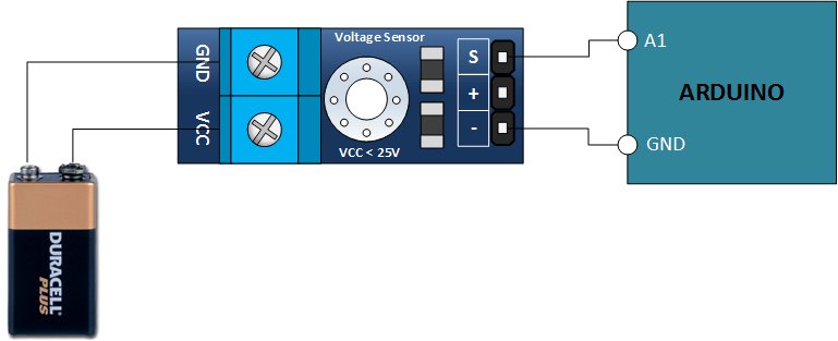
ملاحظة هامة جدا:
هذا المستشعر قطبي .. اي يجب التاكد من توصيل الموجب (+) للبطارية او المحول(مصدر الجهد) على الـvcc والسالب (-) للبطارية او المحول(مصدر الجهد) على الـGND واذا حدث العكس فانه لا يعمل على قياس الفولتية